The Wireless Microphone and IEM Systems for Grease Live!
by Dave Bellamy

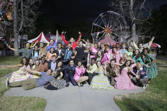
It started as it usually does with a simple phone call. The call was from longtime friend Bruce Arledge. He said that there would be a production of Grease and that he was the Sound Designer. The show would be produced at Warner Bros. Studios Burbank and it would air live January 31, 2016.
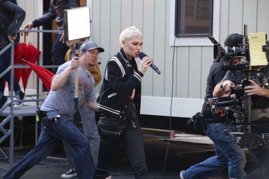
He went on to say that there would be fifty-three wireless microphones required and as yet undetermined quantity of IEMs. The show would take place on multiple stages and that the microphones have to be supported by one antenna system regardless of where they were being used during the show. He also noted that Jessie J would open the show with a walk, singing live, with ear monitors and that she would begin on Stage 26 and end in front of the set of Rydell High School traversing a distance of more than six hundred feet. He knew that we had an antenna system (the Phoenix system) that was capable of successfully doing this type of project. He also said that he and Mark King, the Production Audio Mixer, had conferred and agreed that Soundtronics was probably best suited to do the show. Would we be interested? Jason Bellamy, the Managing Partner of Soundtronics, took the call, thanked him for the opportunity and said we were.
He went on to say that there would be fifty-three wireless microphones required and as yet undetermined quantity of IEMs. The show would take place on multiple stages and that the microphones have to be supported by one antenna system regardless of where they were being used during the show. He also noted that Jessie J would open the show with a walk, singing live, with ear monitors and that she would begin on Stage 26 and end in front of the set of Rydell High School traversing a distance of more than six hundred feet. He knew that we had an antenna system (the Phoenix system) that was capable of successfully doing this type of project. He also said that he and Mark King, the Production Audio Mixer, had conferred and agreed that Soundtronics was probably best suited to do the show. Would we be interested? Jason Bellamy, the Managing Partner of Soundtronics, took the call, thanked him for the opportunity and said we were.
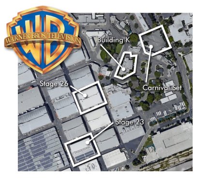
At the first production meeting, with stage plots and a map of the Warner Bros. lot in front of me, I began to become aware of the overall scope of this project. The show would encompass fourteen sets over twenty acres of real estate. I remembered having a conversation with Mr. Arledge and hearing him say that most of the scenes take place on Stages 23, 26 and the Rydell High School set, which on the Warner Bros. map was known as the K building located on the backlot. Another look at the map showed that Stage 26 was almost equidistant between Stage 23 and the K building. The next step was to schedule a site survey where detailed measurements could be taken.
The findings of the survey were far from being favorable, at least from an RF spectrum perspective. The RF environments in Stages 23 and 26 were relatively friendly. Both stages fairly well shielded with wire mesh on the walls and ceiling, Stage 23, being the better of the two. In the K building/Rydell High School, we were not as fortunate. There was next to no RF shielding in this building. The structure offered protection from the sun and very little more. The RF environment in the open areas outside of the structures can only be described as hostile. LA is a huge market with wall-to-wall DTV channels in the 500 MHz to 700 MHz frequency ranges. Channel 19, 500 MHz–506 MHz was the only exception. Every other channel had DTV in it at some level. Additionally, Channel 19 is no bargain. At that frequency, there is usually enough local interference caused by other electronics on stage to raise the noise floor 6 dB to 8 dB or more. In some cases, Channel 19 can be more difficult to work in than a low-power DTV channel.
Luckily, more than seven of the DTV channels that registered on my spectrum analyzer were from out of the area and were legal to use at the Warner Bros. location. I selected the best three of those and that is what we went with. That netted us 24 MHz of dirty spectrum in which we need to get twenty-four microphones to work seamlessly. I remember feeling confident at the time that we could do that, but we needed fifty-three, leaving us twenty-nine microphones short. To make up for this shortfall, we had to find more usable spectrum. The first thing we did was apply to the FCC for special licensing so we could gain access to the spectrum between 944 MHz and 960 MHz. This would buy us 16 MHz of bandwidth that would yield eighteen usable frequencies. The second thing we needed to do was gain at least partial use of the ISM band. This is the band between 902 MHz and 928 MHz. To be able to successfully operate in these frequency ranges, we would need to have the full cooperation of the Warner Bros. frequency coordinator, Ara Mkhitaryan, and that is exactly what we got. He could not have been more helpful. Thanks to him, we were able gain access to 11.5 MHz in the ISM band that would yield fifteen usable frequencies. Let’s see now, 24 + 18 + 15 = 57 and we needed 53.
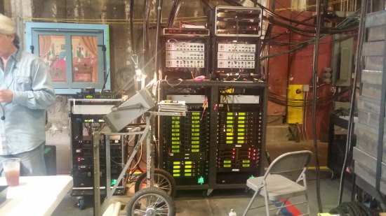
About two weeks after the RF survey, we conducted another survey purely for the purpose of measuring the property. Every stage; the distance between stages, every performance area and the distance between performance areas and every potential cable run. After reviewing my measurements, I decided that along the north wall of Stage 26 would be the best place for the master RF rack. The satellite rack on Stage 23 would also be placed along the north wall near the cable access ports for that stage. The satellite rack for the K building would be located in the tech center behind the Rydell High School hallway set.
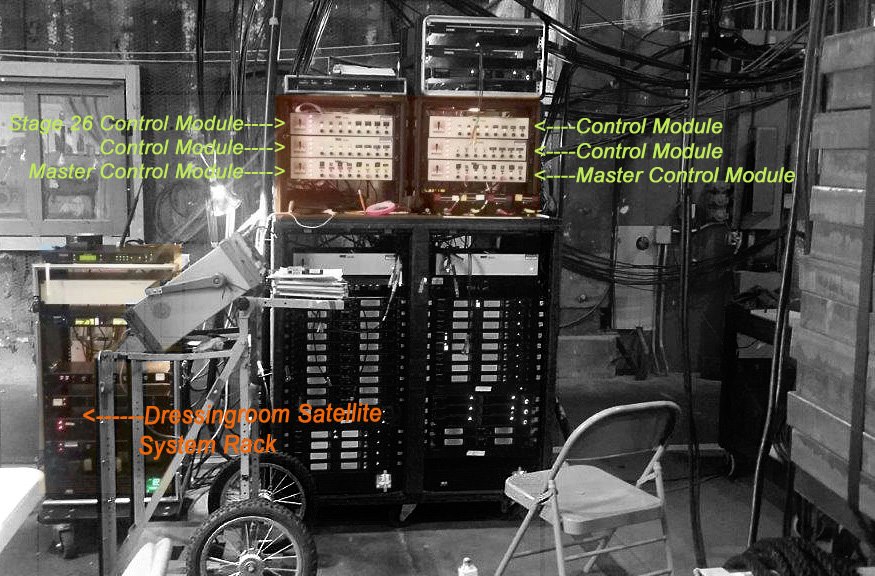
There would be four intermediate cable runs that would link the satellite antenna rack on Stage 23 to the master rack on Stage 26. These cable runs were six hundred feet in length each. There also would be five intermediate cable runs that would link Stage 26 to the K building; four for the satellite system and one of them for the Jessie J in-ear monitor system. These runs would be seven hundred and fifty feet in length each.
The design of the system would be straightforward. We would break the project into four zones: Stage 26, the Dressing Rooms, the K building and Stage 23. Each zone would have a discreet Phoenix satellite antenna system that would operate independently of the other three satellite systems. All four systems would be combined at a master system rack location on Stage 26. Each system would be assigned an RF technician with a spectrum analyzer. I would be responsible for the systems on Stage 26 which would include the Stage 26 satellite system, the Dressing Rooms satellite system and the master antenna system rack which would also be the home of all of wireless microphone receivers. Corey Dodd would be responsible for the K building system and Grant Greene would be responsible for Stage 23 system. All four systems could be monitored from the master rack location on Stage 26. The K building and Stage 23 systems could be monitored locally.

Before we go any further, I think it would be appropriate to provide a brief description of the Phoenix system and some of the advantages of using it, especially in view of the fact that we will be using four of them on this show. We will begin at the antenna. The antenna is connected with a short piece of coax to a four-channel gain adjustable filter set, capable of providing 15 dB of gain. The gain is used to compensate for cable loss and nothing more. The filter set is connected to a much longer piece of coax that runs back to the RF rack where it is connected to a control module. The control module can power the filter set via the coax or power it down if necessary. The control module then feeds a band past antenna distribution amplifier (DA) which can feed up to thirty-two receivers. Since the filter is capable of supplying gain, the length of the coax is all but irrelevant. Two hundred and fifty feet is not considered to be a long cable run. The antenna can now be optimally placed virtually without cable length restrictions. A Phoenix VIII control module is capable of supporting eight filter set/antenna locations. If two Phoenix VIII control modules are used, one feeding the “A” side of the antenna distribution amplifier and the other feeding the “B” side of the antenna distribution amplifier, the system is capable of supporting sixteen filter set/antenna locations. Because each antenna can be optimally placed, the Phoenix system can be tailored to the show and the antennas focused on where the transmitters are actually working during the show. When balancing a Phoenix system, the frequencies in the 500 MHz to 700 MHz range are set at 8 dB below reference gain, the frequencies in the 902 MHz to 928 MHz range are set at 4 dB below reference gain and the frequencies in the 944 MHz to 960 MHz range are set at 2 dB below reference gain. The gain can be further reduced if necessary, either globally at the antenna DA or at individual antenna locations.
Our first official installation day was December 16, 2015. The schedule called for ESU of the entire property by the end of the day on December 17. There would be two dark days, then on-camera rehearsals would begin on Stage 23 on December 20 and continue through the 21st. Two days wasn’t nearly enough time for all that needed to be accomplished. But beginning rehearsals on the 20th was doable. Luckily, the antennas on Stage 23 had already been flown and the intermediate cables had been run. All that remained was to move the satellite rack into place on 23, move the master rack into place on 26 and balance the system through to that point. Stage 23 would require two Phoenix XIII systems. The highrange system would manage the bandwidth between 902 MHz and 960 MHz and the low-range system would manage the 500 MHz to 700 MHz bandwidth. At each antenna would be a dual-range filter set with two discrete antenna inputs. The high side would be fed by a Sidewinder antenna tuned to the 870 MHz to 900 MHz bandwidth. The low side would be fed by a Widowmaker antenna tuned to the 500 MHz to 700 MHz bandwidth. (Both of these antennas are proprietary Phoenix system designs.) This would be a twelve-antenna array system employing twenty-four antennas in all. The satellite rack itself would contain two control modules that fed two 30 dB line amplifiers for the high-range system and two control modules that fed two 20 dB line amplifiers for the low-range system. The outputs of each of the four line amplifiers would feed the corresponding inputs at the master control modules in the main rack on Stage 26. To balance the system would require the implementation of two devices, a Reference Transmitter Kit (RTK) and a Live Motion Simulator (LMS). The RTK is an assortment of transmitters tuned to the center frequency of the passbands being used. The transmitters are built into a small road case within two outputs; a high range and a low range. The RTK is then patched directly into a spectrum analyzer and the amplitude of each transmitter is noted on a system test form. The RTK is then unpatched and an output of the antenna system is patched in its place. The RTK then moves to one of the filter set locations. The antennas are unpatched at that location and the RTK is patched in. The gains are then adjusted until they meet the afore mentioned specifications, 8 dB below reference in the 500 MHz to 700 MHz range, 4 dB below reference in the 902 MHz to 928 MHz range and 2 dB below reference at the 944 MHz to 960 MHz range. The RTK is then unpatched and the antennas reconnected. This is repeated at all antenna locations. The same RTK is used throughout all of the antenna locations on the show. The RTK is also used to balance the intermediate cables between Stage 23 and 26. The specifications for these runs were reference plus 0 dB or minus 1 dB.
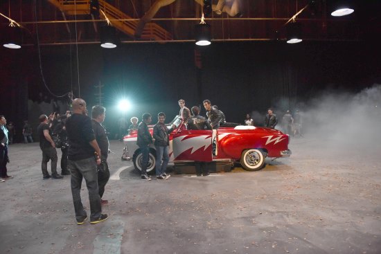
Now we know that all of our lines are balanced but we still do not know how well the antennas are working. To qualify the performance of each antenna, we implement the LMS. This device is placed on the set well within the beam width of each antenna to be tested. Reference transmitters are mounted on the LMS where they are rotated continuously 360 degrees in a circle four inches in diameter. Utilizing the peak hold setting on my analyzer, I can determine if I am receiving the amplitude that I expect to see and if there is parity among all of the antennas in the system.
Looking from more of a theatrical perspective, Stage 23 would be the location of the Frenchy’s House, USO, Auto Shop, Lovers Lane, Drive In and Thunder Road sets. Rehearsals would begin on time and go well. Now it became a matter of installing the rest of the systems while staying ahead of the rehearsal schedule at the same time. Rehearsals would begin on Stage 26, the hub of the design wheel, on the 22nd. That gave two days to complete our work there.
The installation of the satellite systems for the stage and the dressing rooms was fairly routine. Both systems were tuned and balanced to the exact same specifications as the system on Stage 23 had been. There were more antennas involved, thirty-one in all. But that was because both systems shared responsibility for the streets on the east and south sides of the building. The main system on Stage 26 was twelve arrays and twenty-four antennas, just like the on Stage 23. Our primary concern and top priority was the performance of Jessie J’s ear monitors during her opening walk from Stage 26 to Rydell High. The walk wouldn’t be rehearsed until the afternoon of the 27th, but the 25th and 26th were dark days. This meant that the system had to be performing to the satisfaction of the monitor audio boys by the end of the day of the 23rd. This way, if there were issues, we had the day of the 24th to fix them. There were no issues. The system worked seamlessly the time it was first tried and every time thereafter. We could now move onto the K building.
The K building satellite system was the largest of the four systems. It covered the second half of the Jessie J walk (the first half was covered by the Stage 26 and Dressing Rooms systems), the Boys to Men vocals at the halfway point of the walk, the front of Rydell High, the interior hallway of Rydell High, the principal’s office, the carnival set located beyond Rydell High on Midwest Street and Sandy’s house where Sandy would perform “Hopelessly Devoted to You.” The system and the seven hundred and fifty foot intermediate cable runs were balanced to the same specification as the system on Stage 23.
On January 29, we learned that the plans for the finale of the show had been realized. The cast would exit the Carnival set on Stage 26 through the west elephant door singing live. They then would board three awaiting trams that would turn left and drive along the east side of the building, then turn right and drive along the same route as the Jessie J walk was taken, drive past the Rydell High set to the Carnival set on Midwest Street. There they would then step off the trams and dance their way to the center of the Carnival set. They would be singing live the entire way traveling a distance of more than one thousand feet. There were sound systems on each of the trams that were fed track by ear monitor receivers located on each tram. These receivers were set to the same frequency as the transmitter that was used for the Jessie J walk. The antenna system coverage for both the wireless microphones would have to be expanded but not very much. We knew that something would be happening on the east side of the building and we were already covered for that. This meant that only two receive antenna locations would need to be added on the south side of the building to cover the wireless microphones. There was already an ear monitor antenna in place at the southeast corner of the building which covered the south side of the building nicely, which meant that the ear monitor coverage would not need to be expanded.
In the end, our balancing acts payed off. During the dress rehearsal and show, the receive antenna system worked beautifully, all four satellite systems performing in unison. In all, forty-eight filter sets, ten line amps, eighty-two antennas and twenty-two thousand feet of antenna cable were in use by the time the system was completed. It gets better. There were no complaints about the ear monitors, not one. Not bad when you consider that it took only six antennas and seventeen hundred and fifty feet of antenna needed to round out the system.
In closing, I would like to say that Grease Live! was a very worthwhile project and all of us at Soundtronics Wireless would gladly do it again.